Arduino – IR Sensor with Buzzer and LED
In this tutorial, you will learn how to interface Arduino Uno, an Infrared sensor and a piezo buzzer.
Working of an IR Sensor.
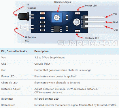
IR LED is one kind of transmitter that emits IR radiation. This LED has the appearance of a standard LED, and the radiation it emits is not visible to the human eye. An infrared transmitter is used to detect the radiation by infrared receivers. These infrared receivers are available in photodiode form. IR Photodiodes are different from regular photodiodes in that they only detect IR radiation. Different types of infrared receivers exist based on voltage, wavelength, package, and other factors.
When used as an IR transmitter and receiver, the wavelength of the receiver must match that of the transmitter. The transmitter is an infrared LED, and the receiver is an infrared photodiode. The infrared photodiode is activated by the infrared light produced by an infrared LED. The photodiode's resistance and the change in output voltage are proportional to the amount of infrared light obtained. This is the IR sensor’s fundamental working principle.
Once the infrared transmitter generates emission, when it arrives at the object & some of the emission will reflect toward the infrared receiver. The sensor output can be decided by the IR receiver depending on the intensity of the response.
Required Components.
- Arduino Uno
- IR Sensor
- LED
- 220 Ohm Resistor
- Buzzer
- Breadboard
- Wires
Connection steps:
1. Connect the components to the breadboard.
2. Connect GND from Arduino to the negative rail of the breadboard.
3. Connect the 5V from the Arduino to the VCC of the sensor.
4. Connect GND from the breadboard to the GND of the IR sensor.
5. Connect pin7 from Arduino to out of the IR sensor.
6. Connect pin8 from Arduino to the positive terminal of the buzzer.
7. Connect the negative terminal of the buzzer to GND.
8. Connect pin9 to the positive terminal of the LED along with a 220 Ohm resistor.
9. Connect the negative terminal of the LED to GND.
Circuit Diagram.
Code:
//Create names for digital pins
#define ir 7
#define buzzer 8
#define led 9
//Create a variable to test against for the sensor
int obstacle;
void setup() {
//Set ir pin for INPUT so that it reads from the sensor
pinMode(ir, INPUT);
//Set led and buzzer to OUTPUT so that they can be turned on/ off
pinMode(led, OUTPUT);
pinMode(buzzer, OUTPUT);
}
void loop() {
//read from the IR sensor and assign value to obstacle variable
obstacle = digitalRead(ir);
//if IR Sensor detects something then turn the buzzer on, and led off
if (obstacle == LOW)
{
digitalWrite(led, LOW);
digitalWrite(buzzer, HIGH);
}
//if IR Sensor does not detect something turn the led on, and the buzzer off
else
{
digitalWrite(led, HIGH);
digitalWrite(buzzer, LOW);
}
}
Result:
Test IR Sensor with different materials and see if you can touch the sensor without triggering it.
You can watch the video below for practical


0 Comments